Vibromera forum

Recent Posts

Pages: 1 ... 3 4 [5]
41
Discussion about Balanset-1 / Re: Integrate Balanset in a old balancyng machine
« Last post by Andrew on July 08, 2018, 12:08:46 AM »
I'll try to answer your questions.
 
1. Our balancing system (Balanset) use test run to get  the balancing (influence) coefficients. First run - to measure initial vibration, 2-nd and 3-d run with adding known test mass - to get  vibration changing and calculate influence coefficients, the correcting weights and place (angle) of mounting the correcting weights.
2.  Yes, in some cases we can adapt hardware with other sensors.  Software can change sensor sensitivity in the "Settings"
3. We can't deliver source code, but we can change user interface color, fonts etc for you requires.
4. We'll glad to help.  We provide support for users to solve the balancing problems using Balkom balancer system.
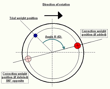
5. We can add polar graphics to our software. Some versions of software has it.

If you have any questions please feel free  tocontact us.
42
Discussion about Balanset-1 / Integrate Balanset in a old balancyng machine
« Last post by Andrew on July 07, 2018, 11:42:35 PM »
Dear Mr.
I am very interested in your balancyng system
I will integrate this system in a old balancyng machine, but please let me know if you can to help me with some requirements

1.- Do yo have some calibration procedure to calibrate sensor with Know mass?
2.- This software can be adapted with other sensors, having data sheet of course
3.- Can you deliver y me a sourse code program in order to modificate some characteristic like colors, font types, windows wide and position aspect.
4.- I will appreciate so much if you can to hep me with this..
thanks and regards,
5.- Can this software to show in polar graphics ?
43
Q1-what sensors are your system using and what sensors would i need to use hard bearings? Do you offer sensors to work with hard bearings?
 
A1 yes, we offer sensors for hard bearing. it's sensors of the force (pressure). See pictures below.


Installing sensors and balancing stand supports construction


Installing sensors


Sensors
Q2 How much movement in the bearings is needed to measure unbalance?
A2  "movement in the bearings" - is it RPM or  deformation of the supports?
Lowest RPM is 400-600 RPM.
 
Q3 Do i need 4 planes to ballance crankshafts and flywheels? Does the plane refer to positions along the shaft being ballanced or does it refer to the axis of measurement?
 
A3 No, to balancing crankshafts 2 planes balancer required, (4-planes no needed), because it's a rigid .
About balancing planes see picture below


Q4 -do i need a degree wheel to find the point of correction after ballancing or will the software and laser locate the position as i turn the crank by hand or is this only possible using a encoder sensor for rotational measurement? Is it possible to get this system with encoder instead of laser tach?
 
A4 Laser is used as zero point sensor only. It can't show point (position) to add correction weight. Software show correction weight position (angle)   from testweight position. You can use degree wheel  to counting angle or encoder to counting angle by software. Using   laser and degree wheel is more simple.


Q5-do you have more pictures, drawings or measurements of the sensors? Are the sensors directional when you fit them to the bearings?
 
A5 Yes, see above

Q6--What is the software requirements? Can i for instance use a windows based tablet?
A6 You can use any Windows from XP to Win10, but not WinCE.
44
Hi! Thanks for prompt reply!

Im new to balancing so i have a lot of questions, hope you can help me with some of them;

-what sensors are your system using and what sensors would i need to use hard bearings? Do you offer sensors to work with hard bearings?

How much movement in the bearings is needed to measure unbalance?

Do i need 4 planes to ballance crankshafts and flywheels? Does the plane refer to positions along the shaft being balanced or does it refer to the axis of measurement?

-do i need a degree wheel to find the point of correction after balancing or will the software and laser locate the position as i turn the crank by hand or is this only possible using a encoder sensor for rotational measurement? Is it possible to get this system with encoder instead of laser tach?

-do you have more pictures, drawings or measurements of the sensors? Are the sensors directional when you fit them to the bearings?

-What is the software requirements? Can i for instance use a windows based tablet?

-i would really like a system similar to the one on the attached photo, where it sits on a milling machine and i have a certain idea how to make the bearings and the drive system but my main concern is to get the bearings to work with the sensors. I have attached a simple sketch of the bearing design im thinking of, based on two pieces of 350x150x20mm aluminium plates, milled with a V-pattern with teflon bearings on top, an area to fit the sensors straight below the V, and mill out the main centre portion to allow for minor movement/vibration and support it with a rubber bushing to prevent excessive movement, what do you think of this idea?
45
>Hi! Can i use this in a crankshaft balancing machine? Do you have pictures of this equipment used in a crankshaft balancer? Does one need to use testweights for balancing? Thanks

Yes, you can use -1 for measuring vibration and finding solution for the two-plane dynamic balancing in a crankshaft balancing machine.
Trial weights are required in any case, because -1 using influence coefficient method. Also sometimes required bobweights. It depends from crankshaft\piston engine construction (pistons number etc) Try to search "crankshaft balancing bobweight" in Internet.
46
General Discussion / Welcome to SMF!
« Last post by Simple Machines on May 28, 2018, 10:49:14 PM »
Welcome to Simple Machines Forum!

We hope you enjoy using your forum.  If you have any problems, please feel free to ask us for assistance.

Thanks!
Simple Machines
Pages: 1 ... 3 4 [5]