Balanset-1 is two-channels balancing system for dynamic balancing of rigid rotors.
Balanset-1 can balance in 1 or 2 balancing planes. It includes two vibration sensors, which will enable you to measure vibration in 2 planes at the same time by one machine run.
We will demonstrate the balancing procedure at our balancing training stand. It consists of electric motor with two disc on the shaft. Electric motor placed on the spring-supported platform. Natural resonant frequency of this system is much lower than rotation frequency of electric motor(3000 rpm - 50 Hz). So, this stand is "after
resonance" type.
There are two vibration sensors which enable you to measure vibration in two planes Balanset-1 balancer includes two vibration sensors(accelerometers), laser phase sensor(digital tachometer), 2-channel USB interface unit with preamplifier, integrators and ADC acquired module, notebook(or other PC) and Windows based balancing software.
Balancing procedure by itself is very simple. It uses 3-run method. In it's first run, (named Run#0 in the program) Balkom will measure the initial vibration of the machine. Then we add the test weight on the first plane of correction and repeat the vibration measurement( Run#1 ). Then we remove the test weight from the 1st
plane, add it to the 2nd plane and repeat the vibration measurement( Run#2 ).
Then software will calculate the mass and it will show us the place(angle) where we have to mount correction weights to reduce the unbalance and vibration.
Theoretically, vibration must be reduced to zero level, but our rotor machine is not ideal and our measurement already has some errors. So, in many cases we need to repeat the balancing procedure. But we don't need to use trial weights again. Once influence coefficients (balancing coefficients) has been saved in the PC memory,
software will use it for next calculations.
Let's take a look at how it really works.
First step is to install sensors at the point of measurement in the platform. The sensors have magnetic base, so we just place it on the steel part of the platform.
Also you can remove magnetic base and mount sensors using screw M4. Vibration sensors placed on the opposite edges of the platform named correction place 1 and correction place 2.
(Detailed theory of dynamic balancing you can see here.)
Then we have to put a reflective mark on the rotor. Phase sensor- tachometer will use this reflective mark to measure phase of vibration and determine the angular position where we have to place correction weights later.
Then run the program.
In the main window you can select balancing type (static 1 -plane of correction or dynamic 2-planes of correction), vibrometer mode, balancing mode, view charts, and view archives when previous measuring data saved.
Before balancing, it is always recommended to check rotor machine technical condition. For this we can use vibrometer mode.
In this mode we can repeatedly measure and analyse vibration of the rotor machine.
Start electric motor.
Click on F9 button - "Run"
In this window shown vibration value and phase. Here Vs is RMS of vibration in the frequency wide range.
V0 is amplitude of vibration on rotation frequency.
Important!
Only V0 will tell us about unbalance value!If V0 is close to zero value - it means that unbalance is close to zero too.
In the chart shown below we can see diagrams of the vibration wave form and spectrum of vibration function.
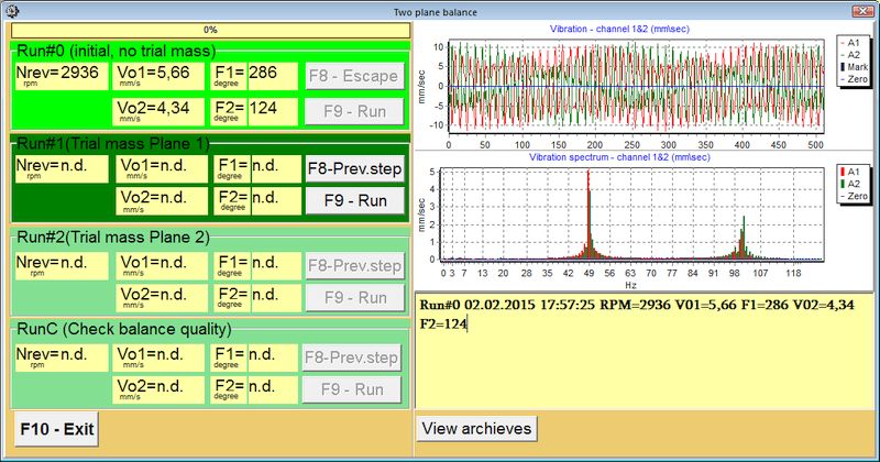
There are 2 harmonic peak - about 5 mm\s on the 50 Hz and about 2 mm\sec on the 100 Hz.
Peak on the 50 Hz characterize unbalance, but peak on the 100 Hz caused by the other reasons.
Here we see V0 is close to Vs, so we can conclude that main reason of the vibration is unbalance.
Now let's try to balance our rotor.
Click F7 - Balancing in the main window.
Input the required data in the window appeared on the screen.
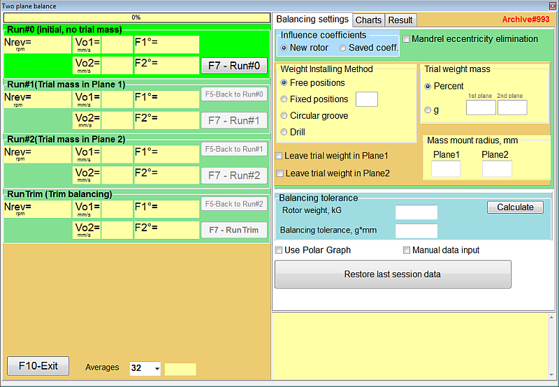
1. Set New rotor if you balance rotor first time or Select rotor if you are going
to balance a rotor which you have balanced earlier.
2. Weight trial mass. We use an electronic weighing scale to measure mass.
3. If you need to split weight select Blades, else select Polar.
4. Set radius of trial mass mounting place.
Now we can begin to balance.
Run#0 measure initial vibration
Start electric motor. Wait for a while until the rotation speed value comes stable.
Then press F9 button Run
Vo1 and Vo2 vibration value on 1x rotation frequency.
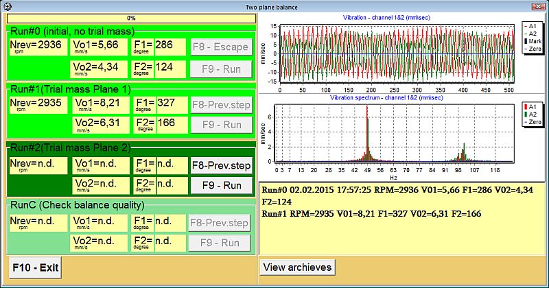
Run#1
Add test weight on the first plane of correction and repeat vibration measurement.
Run#2
Remove test weight from the 1st plane, add it to the 2nd plane and repeat vibration
measurement.
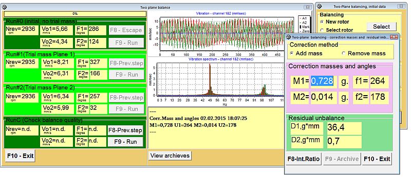
This software will show you the mass and the place of the correcting weights.
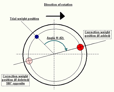
Remove test weight from the 2nd plane and add correction mass M1 and M2 on the
angles f1 and f2 , as shown on the screen shot.
Be sure that you place masses correctly by the direction of rotation
from trial weight place.
Then we should check result of our balancing.
Run machine again (RunC)
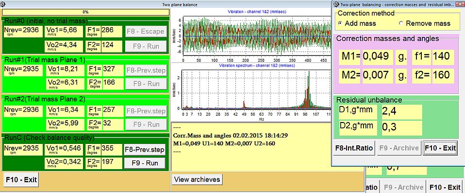
-------
We can see that vibration caused by the unbalance reasons (on 50 Hz frequency) is
reduced to more than 10 times.
We can make a next trim step and add new correcting weight M1=0.049 g.
M2=0,007 g is too small, so we don't need to add it. (But you may add this weight
to obtain more precise balancing)
Then check result again
RunC-2
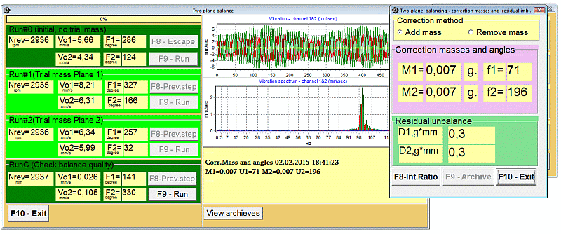
Vibration in the 1st correction plane is reduced to more than 200 times and in 2nd
plane - more than 40 times.
 Recent Posts